This post is a followup of VeloPads: DIY paper-thin, velocity-sensitive drum pad. When I wrote that post, Micah and I had built several prototype MIDI drum pads and we’d left hardware improvements as the #1 thing to do next.
We’ve since spent some time improving the hardware design. This post will describe the process we went through as well as our solution.

We had several goals in mind when improving the hardware. Ideally, the new design would satisfy the following criteria:
- Smaller form factor. The original prototype was much more bulky than traditional drum pads, and for no good reason. The ideal dimensions for a drum pad seem to be around 1.5”2. This is large enough to get a comfortable feel underneath a single finger but not large enough that space feels wasted.
- Consistent sensitivity. On the electrical side of things, every pad should have a near-identical resistance range. This way the pads are replaceable, and we won’t need to compensate in the software or circuitry for pads that are more or less sensitive.
- Easy to make. While we don’t intend on mass producing VeloPads, I wanted us to be able to DIY a new pad in less than 5 minutes with minimal effort and concentration.
- Feel good. A drum pad that’s literally as thin as paper is a novelty, but, in my opinion, doesn’t feel great to the touch. I’d like the pad to feel like it compresses or squeezes for better haptic feedback.
- Inexpensive to produce. In reality this isn’t much of a concern, since the materials we’re working with are quite cheap. See the materials section of the original post for the price breakdown. However, all other things being equal, using less material is better.
The Materials
With these unarticulated thoughts floating dimly around my brain, I went to a local crafts shop to peruse.
I ended up purchasing the following materials to experiment with:
- X-Acto Knife - $4
- Self-healing cutting mat, 9” x 12” - $8
- 6” Straight Edge - $4
The Designs
For me, the first step was to simply experiment with a variety designs. The domain was new to us with many unknown unknowns, so it seemed reasonable to just try many things quickly and collect learnings.
Redesign #1
The first redesign looked like this:
Photo of two-layer design
This design has two strips of conductive tape on the same layer, with a layer of velostat on top to connect them. I liked this idea because it uses minimal conductive tape and is very easy to make.
Unfortunately, it didn’t work very well when tested end to end in as a MIDI controller. Only relatively heavy taps would register, and even heavier taps didn’t sound noticeably louder. The sensitivity was terrible.
We verified this by uploading code to our Arduino to write the actual resistance values to the serial output (using the Arduino as an ohmmeter). Then, as we pressed and released the pad, we could see how the circuit’s resistance actually changed, and we could compare this to that of our original prototype.
Here are the measurements we took:
| Design | Max | Min | ||
|---|---|---|---|---|
| Prototype | 22kΩ | 10Ω | ||
| Redesign1 | 10kΩ | 3kΩ |
As you can see, the prototype actually had a much higher maximum resistance and a lower minimum resistance than this first redesign. Remember, these resistance values translate directly to MIDI velocity, so a reduced resistance range means a reduced velocity range.
In this way, we learned to empirically measure the sensitivity of our pad designs. This let us prune bad designs without testing the controllers end to end, which saved us time.
Redesign #2

The photo above shows three different designs (rows) each consisting of three layers (columns). If we take the first row, we can see that the first layer is a coil of wire snaking horizontally from top to bottom. The middle layer is simply a square of velostat, and the last layer is a coil of wire snaking vertically from left to right. These layers will get stacked together, with the last layer flipped so the wire coil is on the inside of the sandwich.
The theory with this design is that when pressure is applied, the crisscrossing wires form a grid of contact points separated by velostat. This grid of contact points should allow resistance to be even anywhere on the pad, and it should provide a low minimum resistance.
We weren’t sure how the grid of contact points would affect the maximium resistance. We also weren’t sure how this pad would feel to the touch, since wire is thick relative to our flat conductive nylon.

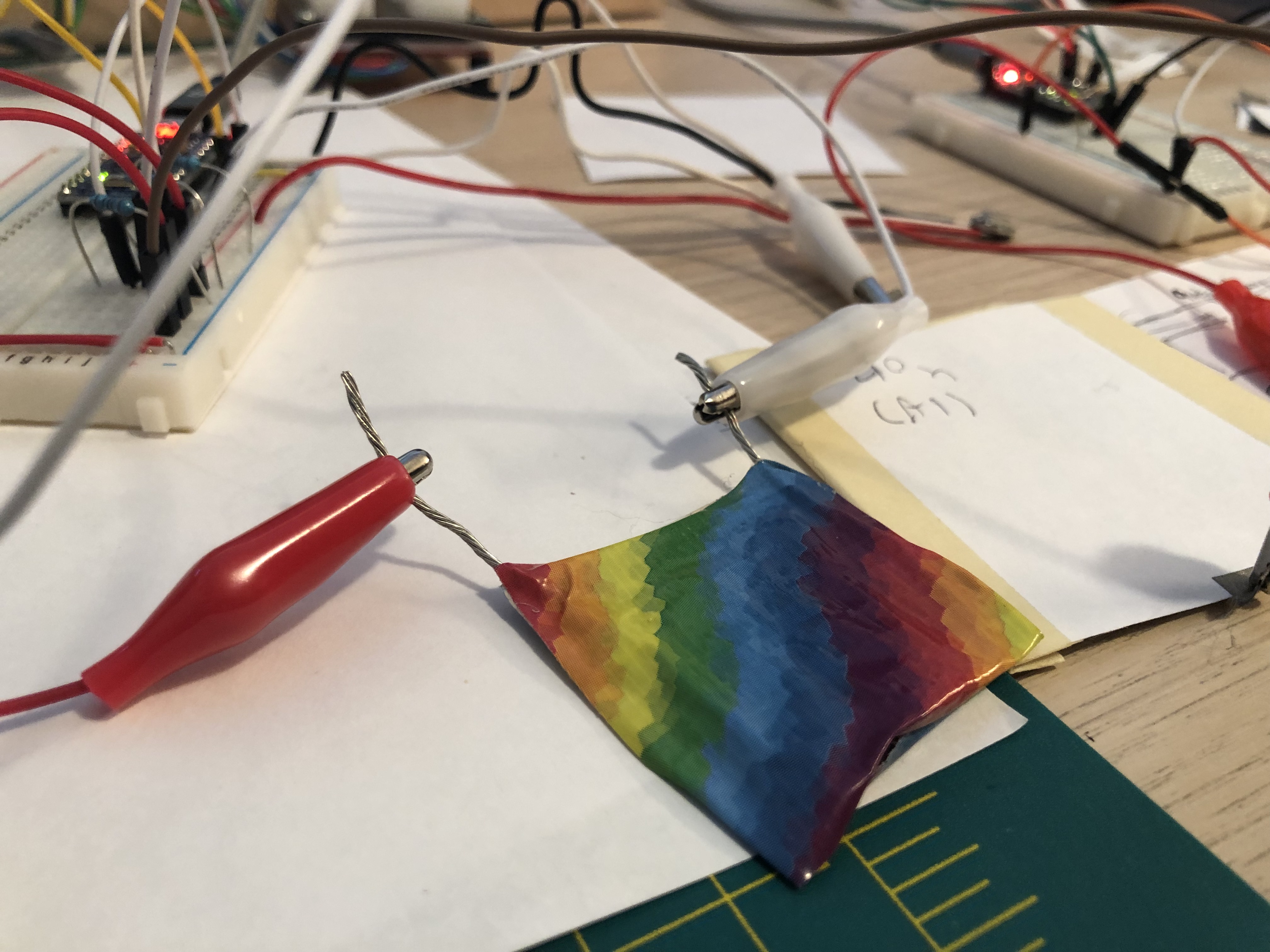 Micah’s completed rainbow pad.
So, how was the sensitivity, and how did it feel?
The sensitivity was as good as our original prototype, which is exactly what we were hoping for. This meant it could respond well to light taps as well as hard presses.
However, when pressing the pad you could definitely feel the wire inside. In practice this probably wouldn’t be very distracting, but we were curious if we could get a similar form factor and sensitivity with a completely flat surface.
Redesign #3
For our next attempt, we tried to take the best of Redesign #2 with its many contact points, using our flat conductive nylon instead of round wire.
The internals look like this:

Sure enough, we were getting great sensitivity readings from our Arduino ohmmeter with low minimum resistance and a high maximum. And it felt thin and flat, definitely not like pressing on wire.
Redesign #3 was the clear winner in terms of sensitivity and feel. It requires two full squares of conductive tape though, which makes it somewhat more time consuming and tedious to build. This is primarily because I don’t have good fingernails for peeling lots of conductive tape :)
Conclusion
Now that we have a good, reproducible design for the pads, it should be very straightforward to produce enough of these pads for a full drum kit. I’d also like to experiment with an additional layer of felt or other material on top of the pads for a better feel.