Last Wednesday, my friend Micah and I had a friend-hackathon where we hacked together paper-thin and velocity-sensitive drum pad MIDI controllers.
Here’s a quick demo video of what we made at by the end of the day:
It was a fun process, and it was gratifying to end the day with something that actually worked, although we left plenty of room for improvement.
In this post, I’ll outline how to build your own pressure-sensitive MIDI pad. This might be a good project for you if you’re interested in a fun, inexpensive project to get you into Arduino, MIDI, or circuitry.
As a disclaimer, I’m not an expert on any of the topics in this article. If there are any inaccuracies in this post, please let me know :)
References
- Arduino code
- Circuit Diagram
- To convert the MIDI signal into audio, you’ll need to install a DAW (Digital Audio Workstation. I use Logic Pro, but for a free option, consider REAPER. (Fun fact: REAPER was created by Justin Frankel, the creator of Winamp.)
Materials
Expect to spend $20-25 on materials, which should easily be enough to make ~12 pads (we only made 2). Most materials are common, so you may already have them lying around. If not, the one-time purchase will give you plenty for future projects.
-
Arduino Pro Micro - $9
- If you don’t want to bother with soldering headers onto the board, you can look into preassembled boards for a bit more money.
- These things are great because they’re tiny: less than 1.5” x 1”. And you can get great bulk deals.
- Velostat Sheet - $5
- Conductive Nylon - $4
-
Alligator clips - $4
- These worked great for clipping onto the conductive nylon.
- We used alligator to female jumper wires, so we could easily plug our male-to-male wires into the female part when integrating into our circuit.
In addition, you’ll want the following common equipment. I won’t price these out since they’re cheap and there’s a good chance you already have them.
- Breadboard
- Male to male jumper wires
- 10kΩ resistors - you can experiment with different resistor values, but this is what we used.
- Micro USB cable - Let’s face it, you have fifteen of these lying around the house.
- Scissors or an X-Acto knife
- Card paper or cardboard
- Masking tape or any non-conductive adhesive
Arduino Pro Micro
Arduino Pro Micro is a tiny microcontroller with a handful of analog inputs and an onboard USB transceiver. They’re less than $6 each when bought in packs of 3.
We originally tried to use an Arduino Uno, which has no such USB transceiver. Because of this, the Uno can’t communicate using MIDIUSB, and therefore can’t be recognized as a MIDI device.
Velostat
Velostat is the hero here. It comes in film-like sheets that can be easily cut and folded. When substituted into a closed circuit in place of wire or other conductor, it acts as a dynamic resistor whose resistance decreases as more pressure is applied. This means that you can measure the resistance of your circuit to determine the relative pressure.
Velostat is a cool material and seems to be coming up in the wearables space to make things like pressure sensitive fabric.
Conductive Nylon
We really could have used any conductor here: wire, copper tape, etc. This particular nylon is nice because it has conductive adhesive on one side, making it quite easy to work with.
It’s also quite thin at 8mm. In the future, I’d like to experiment with how wider tape (this, for example) affects the sensitivity of the pad.
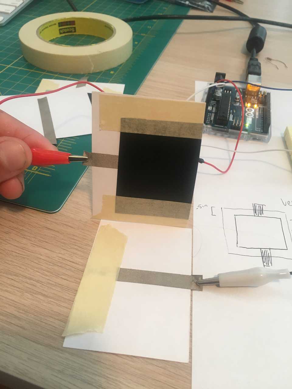
The pad hardware
For our hackathon, we were okay with quick and dirty pad hardware. We wanted to know that the concept worked, so we used cheap parts and quick measurements, leaving refinement for future iterations.
- Cut a piece of card paper into two halves
- Run conductive nylon down the center of each half. Make sure the conductive nylon overhangs the paper by at least an inch, so you have access points for the alligator clips.
- Cut a rectangle of velostat that will fit inside of a card paper half.
- Tape the velostat over the conductive nylon on one of the card paper halves.

That’s it! Now you can attach alligator clips to the access points at each end of the conductive nylon and integrate your velostat pad into the circuit.
The Circuit

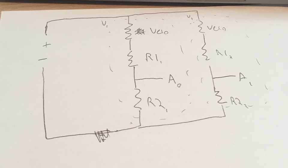
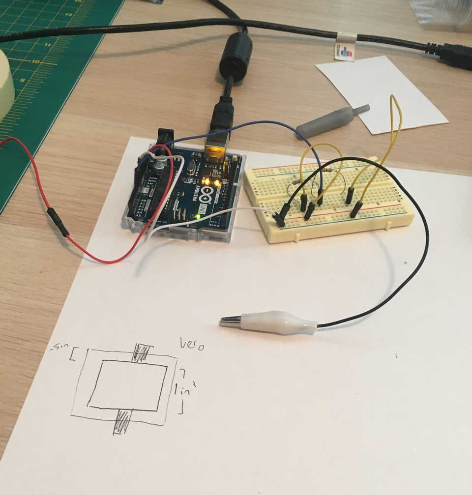
The circuit we came up with is simply that of multiple ohmmeters wired in parallel, with our Velostat pad hardware in place of each unknown resistor. The resistance values are then read through different analog inputs on the Arduino.
To explain the circuit diagram above for those less experienced with circuitry:
+is wired to the Arduino’s “VCC” pin, which supplies 5V of voltage.- A0 and A1 are simply wired to the A0 and A1 pins on the Arduino.
-is wired to the Arduino’s “GND” pin, which is ground.
The Software
The code for our Arduino sketch lives here: https://github.com/jonmellman/VeloPads/tree/master/Velostat_Resistance_Reader
Code Explanation
First, in the VelostatPad.h file we declare an external struct to maintain the state of each pad:
struct VelostatPad {
  int analogPinNumber;
  int currentVelocity;
  bool isOn;
};
Now in our main file, we can instantiate our VelostatPad abstraction in the Arduino setup method:
const int NUM_VELOSTAT_PADS = 2;               // Adjust based on the number of velostat pads wired in your circuit.
struct VelostatPad velostatPads[NUM_VELOSTAT_PADS];

void setup()
{
    for (int i = 0; i < NUM_VELOSTAT_PADS; i++)
    {
        struct VelostatPad pad = {
            i,
            0,
            false
          };

        velostatPads[i] = pad;
    }
}
Simple so far: we’re creating an array of VelostatPads and initializing it with pads in the off setting.
Now we need a method that can take a pointer to the pad object and update its state based on the respective analog input value. For example, we need to transition a single pad to the on state when it is pressed. Once we have this method, we can simply iterate over velostatPads on each Arduino loop and update each pad’s state.
Consider a simple implementation of this updateState method, which leaves lower-level methods unimplemented (readResistanceFromPin, getVelocityFromResistance, noteOn, and noteOff). We’ll implement them next.
void updateState(struct VelostatPad *padPointer)
{
    const int RESISTANCE_THRESHOLD = 6000;
    float resistance = readResistanceFromPin(padPointer->analogPinNumber);

    if (!padPointer->isOn && resistance < RESISTANCE_THRESHOLD)
    {
        // Low resistance means pressure on the pad, so send MIDI notes.
        padPointer->currentVelocity = getVelocityFromResistance(resistance);
        padPointer->isOn = true;
        noteOn(0, 36, padPointer->currentVelocity);
    }

    if (resistance >= RESISTANCE_THRESHOLD)
    {
        // High resistance means no pressure. Stop sending MIDI notes.
        padPointer->currentVelocity = 0;
        if (padPointer->isOn)
        {
            padPointer->isOn = false;
            noteOff(0, 36, 0);
        }
    }
}
We read the respective resistance from our circuit (remember our Velostat pad’s property: its resistance is inversely related to pressure!), and then perform logic based on the resistance value. If the resistance is sufficiently high, we turn the pad on. If it’s not, we turn the pad off.
Note that it’s possible for the circuit to be closed even when the pad isn’t pressed. This is because e.g. gravity is pushing the velostat into the wire. To ensure the pad doesn’t emit MIDI notes in this case, we define a ceiling value RESISTANCE_THRESHOLD. If the measured resistance is higher than this threshold, we’ll consider the pad depressed.
Now let’s look at readResistanceFromPin:
float readResistanceFromPin(int pinNumber)
{
    float rawAnalogInput = analogRead(pinNumber);

    if (rawAnalogInput == 0)
    {
        return MAX_RESISTANCE_OHMS;
    }

    /*
        Arduino voltage measurement is relative to V_IN, and mapped to a 0 - 1023 scale.
        For example, if the pin reads its maximum of 1023 then the actual output voltage is the same as the input voltage (5V).
        https://www.arduino.cc/reference/en/language/functions/analog-io/analogread/
     */
    float Vout = (rawAnalogInput * V_IN) / 1023.0;
    float outputResistanceOhms = REFERENCE_RESISTANCE_OHMS * (V_IN / Vout) - 1;

    outputResistanceOhms = min(outputResistanceOhms, MAX_RESISTANCE_OHMS); // Clamp output value

    return outputResistanceOhms;
}
Here we read the output voltage on the given pin and then use this to calculate the velostat resistance (assuming, as constants, the original input voltage as well as the value of our reference resistor).
To understand the math, it helps to understand the simple voltage divider circuit. In such a circuit, the output voltage is relative to the input voltage and the circuit’s two resistor values. In our case, we know the output voltage (it’s what our analog pin is reading), the input voltage (5V on our Arduino) and one of the resistor values (10kΩ), so we can derive the second resistor’s value (the velostat resistance).
The exact equation we use to solve for the Velostat resistance is that given in a resistive divider circuit:
Note that our code returns early if the measured resistance is 0 to avoid a divide-by-zero error later on.
Great! Now let’s look at the getVelocityFromResistance method, which maps this measured resistance to a MIDI velocity.
int getVelocityFromResistance(float resistance)
{
    return 127 - (resistance / MAX_RESISTANCE_OHMS) * 127;
}
Here we take the resistance and map it to an inverted linear scale, such that resistance of 0 is the MIDI max velocity of 127 and resistance of MAX_RESISTANCE_OHMS produces a velocity of 0.
Note that this velocity curve may be overly simplistic. It assumes that the lightest tap on the velostat pad would produce a velocity of 1 and the heaviest tap would produce a a velocity of 127. In other words, it is totally uncalibrated to the real-world resistance values of the velostat pad and the real-world pressure of a human touch.
Now the noteOn and noteOff methods which emit the actual MIDI data from our Arduino:
#include <pitchToFrequency.h>
#include <pitchToNote.h>
#include <frequencyToNote.h>
#include <MIDIUSB_Defs.h>
#include <MIDIUSB.h>

// First parameter is the event type (0x09 = note on, 0x08 = note off).
// Second parameter is note-on/note-off, combined with the channel.
// Channel can be anything between 0-15. Typically reported to the user as 1-16.
// Third parameter is the note number (48 = middle C).
// Fourth parameter is the velocity (64 = normal, 127 = fastest).
void noteOn(byte channel, byte pitch, byte velocity)
{
    midiEventPacket_t noteOn = {0x09, 0x90 | channel, pitch, velocity};
    MidiUSB.sendMIDI(noteOn);
    MidiUSB.flush();
}

void noteOff(byte channel, byte pitch, byte velocity)
{
    midiEventPacket_t noteOff = {0x08, 0x80 | channel, pitch, velocity};
    MidiUSB.sendMIDI(noteOff);
    MidiUSB.flush();
}
These are simple wrappers around helpful MIDIUSB library calls. With these parameters we can control the channel, pitch, and velocity of the MIDI notes we send.
Putting It All Together
With the pad hardware added to the circuit and the software uploaded to the Arduino, you can now use your drum pad!
Open the DAW of your choice and create a software instrument like you would for any other MIDI controller, then tap the velostat pad to produce velocity-sensitive sounds!
Next Up
We didn’t do any “fit and finish” as a part of our hackathon, which means there’s lots of room for improvement and refinement.
- Improve the form factor. Our prototype pads were quite large and unwieldy, with wire on two of the four sides. Ideally the pads would be smaller (around 1in2) with wire on just one single side to be less intrusive.
- Improve the tactile feel. Our prototype pads have an exterior of card paper, and, while it’s a fun novelty to have a MIDI controller that’s literally “paper-thin”, I think it would feel much better with a padded or foam surface. We would need to experiment with whether this interferes with the pad sensitivity.
- Calibrate the software velocity. A light tap should produce a soft sound, and a heavy tap should produce a loud sound. While this actually worked fairly well in our prototype, we’ll need to calibrate the velocity curve as we redesign the pad hardware to use less velostat.
- Print the PCB for cheap in China. I think this would be fun :). I’ve heard that it’s easy and cheap to get high-quality circuits printed and shipped from China. I’m curious to try this out, especially since these circuits are relatively simple.
- Make a clean and functional drum pad. In my view, this requires at least three sets of pad hardware wired in parallel: one for kick drum, high hat, and snare.
Update: You can read the followup in VeloPads II: Improving the Hardware
